
R I C E U N I V E R S I T Y A D D I T I V E L A B
Grain Boundary Control
Skills Demonstrated:
First Principles Thinking
Process Development
Rapid Prototyping
3D Printing
Fusion Modeling and G-Code
CNC Milling

Research Overview
Research Objective: Create the first aluminum bicrystal with a planar grain boundary separating the two aluminum grains
Bicrystal Method: (1) 3D print master, (2) cast plaster mold, (3) forge bicrystal with furnace, (4) machine bicrystal into required sample dimensions, (5) sample etching to remove surface imperfections
Process Generation: Proprietary process developed by a PhD student, a material science student, and myself
Research Purpose: Grain boundary control in materials is a growing field in additive manufacturing. Specifying grain boundaries can lead to superior shock absorption properties for missile defense and ISS/satellite external structure
(Image on right shows samples made for the Army Research Labs. Samples were hypersonic shock tested.)
From Theory to Execution
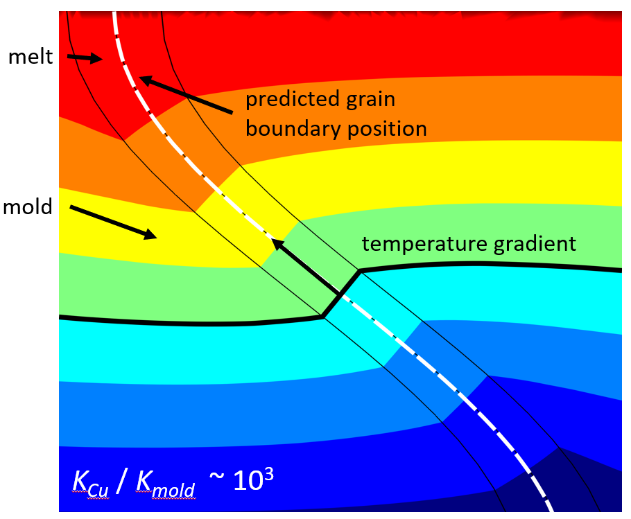
The proprietary process was developed by a PhD student, a material science student, and myself. It was the first time the theorized grain boundary control method (shown in the image to the left) had been executed in a lab. Developing the process required copious iteration and a high precision.
T H E P R O C E S S

(1) 3D Print Master
Master is generated using Stereolithography (SLA) 3D printing. The crystal is highly sensitive to the dimensions of the master. A cusp too large between the two crystals or too small will cause the crystal to leave the metastable region and form multiple grains.

(2) Cast plaster mold
The 3D printed master is placed inside of the mold housing. Plaster is added then left to dry. Then, the mold is heated and the 3D printed master melts away. Finally, high purity aluminum is melted in a crucible and delicately poured into the mold.
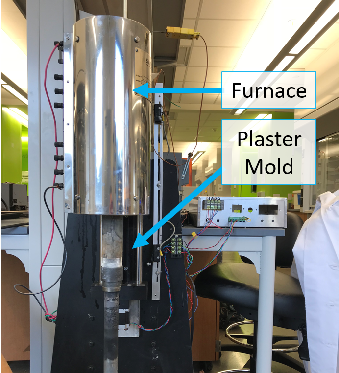
(3) Forge bicrystal with furnace
As the mechanical engineer on the team, I was tasked with designing the actuated furnace and machining methods. The furnace (labeled in the image to the right) starts low to the ground and moves upwards at a rate of 1 inch per hour to grow the two aluminum grains in a controlled and repeatable manner. A vacuum pump is also attached to the furnace to lower the pressure in the crystal growth chamber to reduce crystal impurities.


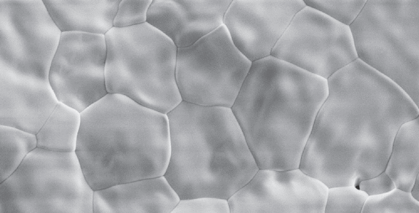
Two seed crystals develop in the graphite chill, one in each leg (shown in light and dark gray in the above left image). Then, each crystal grows independently until they meet and initiate a grain boundary. The transition from two independent legs to tangent crystals is the highest risk step of the process.

(4) Machine bicrystal into required sample dimension
Machining a bicrystal is more challenging that stock aluminum billets because the metal is softer and requires slower feeds and faster speeds. I wrote the G-Code that cut the samples from the bicrystal.

Before Machining

After Machining
5) Sample etching to remove surface imperfections
When the bicrystal is machined, it creates microcracks in the sample surface. The samples need to be etched to remove the microcracks and prepare the sample for hypersonic shock testing. (No images available because process is proprietary.)