
Engine Mice - J85 Engine Operability Testing
Skills Demonstrated:
Solver Creation
3D Scans
Solidworks Modeling and Analysis
3D Printing
Large-scale Testing

Design Overview
Engine mice (shown in silver in the image to the left) attach to the inner nozzle flaps of an adjustable area nozzle.
They are test parts that are used to constrict the area at the throat of the engine to get stall data across the engine operating environment.
The engine mice were 3D printed out of Inconel, a nickel-based high temperature alloy. I designed these parts as my summer internship project at Boom.

Sizing
I created a solver in NPSS (a NASA engine performance software) to find choke area at the nozzle throat for different shaft speeds
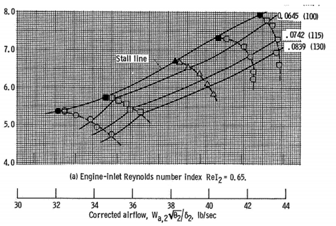
NASA Compressor Map for similar engine test conditions
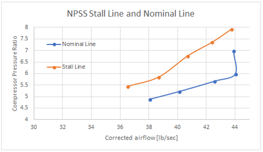
Stall and Nominal line from NPSS Solver Results described above. Compressor map shown on left was compared to plot above to verify solver results

Design
I designed an aerodynamic, tight tolerance wedge that fastened to the nozzle flap. I generated a surface to interface with the nozzle flap by scanning the nozzle flap and creating a surface from the point cloud. I then analyzed the geometry in SolidWorks and 3D printed a mock-up to check fit.

Limit Stress Check

Modal Check

Buckling Check

Testing
Engine mice achieved intended purpose at USAFA test cell. Data from engine operability testing informed engine face distortion requirements and XB-1 flight envelope. I had the opportunity to assist with testing by monitoring temperature limits in the control room (shown in the image below)
