
Jet Engine Heat Shield
Skills Demonstrated:
Leadership
Surfacing
Metallic Material Selection
Solidworks Modeling
Sheet Metal Design
Engineering Buyoff During Assembly
Purpose
Reduce maximum temperatures seen by the aft fuselage frames and skins
Split the secondary flow into hotter and cooler streams
Provide radiation barrier
Shown in the images to the right are results from the aft fuselage thermal model. The yellow box indicates the region of the aft fuselage that the internal heat shield protects. The red regions are locations where the titanium structure has half of its room temperature strength

No Heat Shield

With Heat Shield
T H E J O U R N E Y
Harsh Operating Conditions Resulted in Multiple Design/Analysis Cycles
THERMAL GROWTH - The heat shield reaches a temperature of 1000 F. As a result, the heat shield grows 0.25” along its length. The engine grows 0.5” along its length. The differences in thermal growth between the engine and the heat shield strain the attachment clips
SONIC FATIGUE - The noise from the engine and exhaust plume cause the thin metallic skins of the heat shield to undergo high-cycle fatigue
VIBRATION - The heat shield must be able to withstand 300 Hz vibration with an amplitude of 0.1”
Internal Heat Shield Design Iterations

Iteration 1

Design

The titanium heat shield was attached to the engine on the fwd and aft edges. The fwd attachments were rigid and the aft attachments were flexures to take up thermal growth
Show-Stopper

The rigid fwd attachments picked up engine vibration that resulted in a 250g mode
Iteration 2

Design
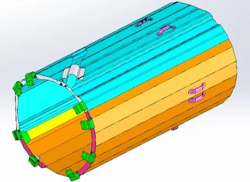
The aft attachments moved to a nearby aft fuselage frame. We thought that with the stiffer mounts attached to a frame, we would be able to handle engine vibration better. The heat shield became faceted for ease of manufacturability.
Show-Stopper

The fwd clips yielded due to lateral engine vibrations. If we made the clips stiffer, they would pick up more lateral engine vibration and fail sooner. If we made the clips thinner, the thermal stresses would cause the clips to fail sooner. Stalemate.
Iteration 3

Design

We switched to frame attachments for both fwd and aft clips. We also split the heat shield into two discrete cantilevered sections. This change allowed the heat shield to grow freely. The skins remained just stiff enough to withstand sonic fatigue and the vibration environment
Analysis Results

The results above show the deflection of the heat shield at 1000 F. The deflection bands shown are a result of thermal growth alone.