T E S T E X P E R I E N C E
Inlet Duct Testing
I conducted the test of a representative section of the 11 ft long, carbon fiber composite inlet duct. The purpose of the test was to correlate the physical behavior duct with the predicted stains from the FEM. This was the first structural bench test at Boom Supersonic.
Instrumentation:
LVDT
Strain gauges
Pressure Transducers
Lessons Learned:
Our analysis is conservative: the structure was able to handle 3x the predicted pressure before the first failure mode was present
Carbon Fiber Composites that are 4/C/4 or thinner are porous and need to be fuel sealed if in a fuel bay

Inlet Duct Testing Setup
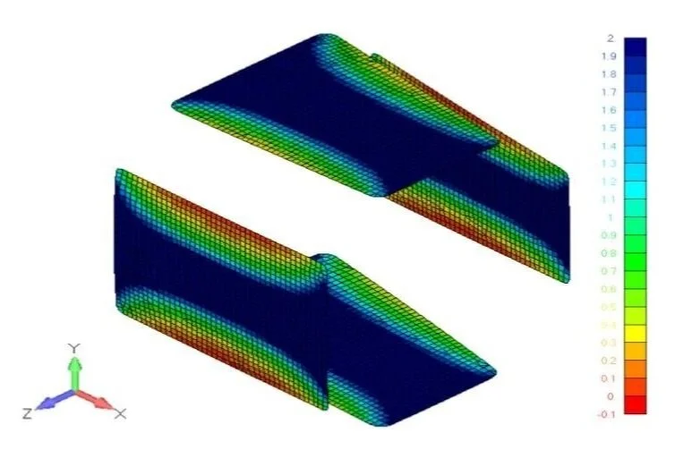
Core shear failure at core ramps predicted to occur at 9.5 psig

Took inlet duct to failure at 34 psig. Core shear is present in test article as shown in the picture above
Nose Landing Gear Drop Test
Drop Testing Overview
XB-1 uses air-oil (oleo) shock absorbers in the nose and main landing gear. These oleos transform vehicle descent energy into heat via turbulent fluid flow across small orifices during landing. The oleo needs to be tested across potential flight conditions to determine nose landing gear parameters such as initial air pressure in the oleo, oil metering speeds across oleo stroke, gas volume compression ratio, and tire pressure. These parameters are predicted using advanced dynamic models and MATLAB 2 mass-spring-damper analysis tools and confirmed through test by simulating landing events with a landing gear drop rig.
My Role
The drop test team consists of 6 engineers across a 4 month test program. My role was to characterize the tire. The nose landing gear contains an oleo and a tire, therefore making it a two mass-spring-damper system. In order to predict parameters for the full system, the tire’s spring and damper constants needs to be characterized independently. I determined that the best way to collect tire compression over time data from landing gear test drops was with a high speed camera (video footage shown above). I procured a state-of-the-art high speed camera capable of taking high resolution video at 2000 fps and a telephoto lens to improve image quality. I then used a motion tracking software to track a retroreflective dot placed on the wheel axis. From there, I was able to process the compression data and generate the plot shown to the right.

Fiberglass Blade Seal
I tested a blade seal that attached to the exterior of the aircraft and sealed the engine bay.
Test Purpose:
Corelate blade seal actual deflections to FEM predictions
. Develop install tooling based on force needed to deflect the blade seal to nominal position on aircraft
As evidenced by the picture to the right, this is a quick and dirty test I conducted. We needed accurate results quickly to inform the aircraft build. However, I did not sacrifice data quality for speed. The blade seal (shown in gold with yellow tag) is held down against the table. A screw jack with a load cell in line is mounted to a metal metrology block. The screw jack and load cell push the vertical piece of wood against the blade seal. The dial indicator is carefully placed perpendicular to the blade seal and measures deflection.

Blade seal shown in gold with yellow flight tag. Test conducted in an afternoon to get quick results to inform aircraft build.