
XB-1 Outboard Inlets
Designed and integrated three mixed compression, Mach 1.6 inlets on the supersonic demonstrator jet with a team of four.
I owned the structural design of the outboard inlets and executed the detailed design of 80 unique parts. I leveraged the ambitious attitude of the company to put myself in a leadership position and take on challenging design tasks. Due to a compressed schedule, I delicately balanced executing design tasks, managing a three person team, and supporting the aircraft build on the shop floor.
S K I L L S D E M O N S T R A T E D:
Leadership
Surfacing
Conceptual Structures Design
Solidworks and Catia Modeling
FEM Analysis
CPD
Fabrication
Engineering Buyoff During Assembly

High-Efficiency
Aerodynamic Surfacing
I had the opportunity to execute aerodynamic surfacing for the inlets in Solidworks and Catia. The surfaces I generate were driven by curvature-controlled splines and lofted area-controlled profiles. The surfaces were then analyzed for performance and efficiency with CFD.
Wind tunnel testing demonstrated that the outboard inlet achieved an efficiency of __% and there was extremely low variation between CPD predictions and Wind Tunnel Data (as shown in the image below).

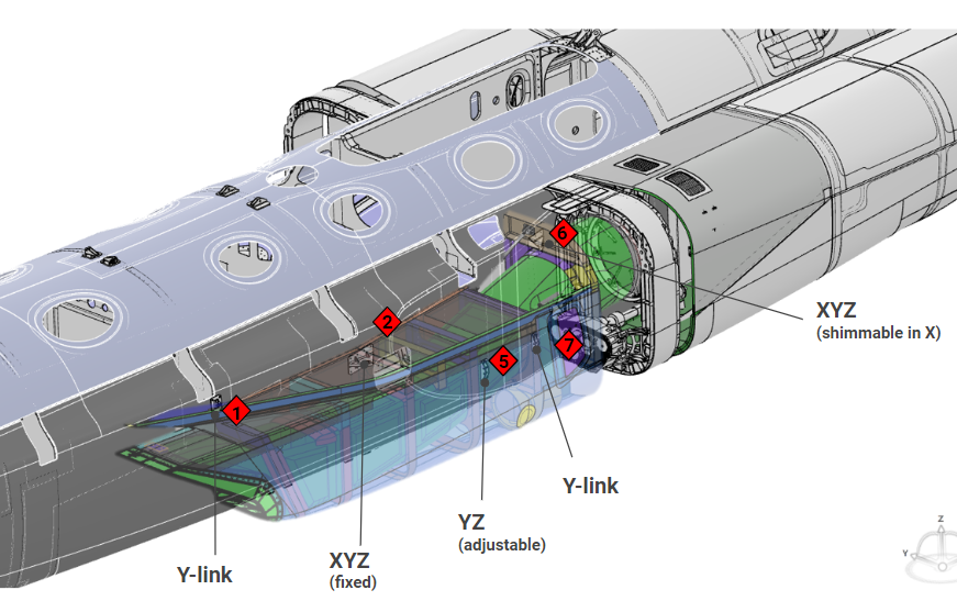
Initial Structural Layout
Once we validated the loft surfaces, we laid out the composite primary structure and mechanism conceptual designs. The layout included frames that gave stiffness to the inlet duct and nacelle components, as well as actuated ramps and doors for optimizing engine efficiency across the flight envelope. The deflections between the inlets and the fuselage were high. As a result, determining constraints of the inlet attachment points was one of the most challenging aspects of the design.
The under-wing inlets deflect outboard and upwards on the order of an inch. This deflection led to challenging sliding interfaces between the inlet and the fuselage and between the inlet and the wing.
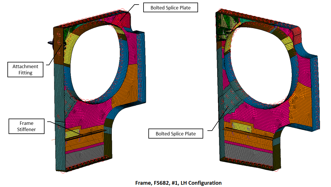
Optimized Carbon-Composite Laminates
Once we had a conceptual design that closed, we proceeded to optimize all primary structure to reduce weight. Each colored region in the picture to the right indicates a different ply count. By reducing ply counts to only what was necessary for each region, we were able to reduce weight of frames by 22%.
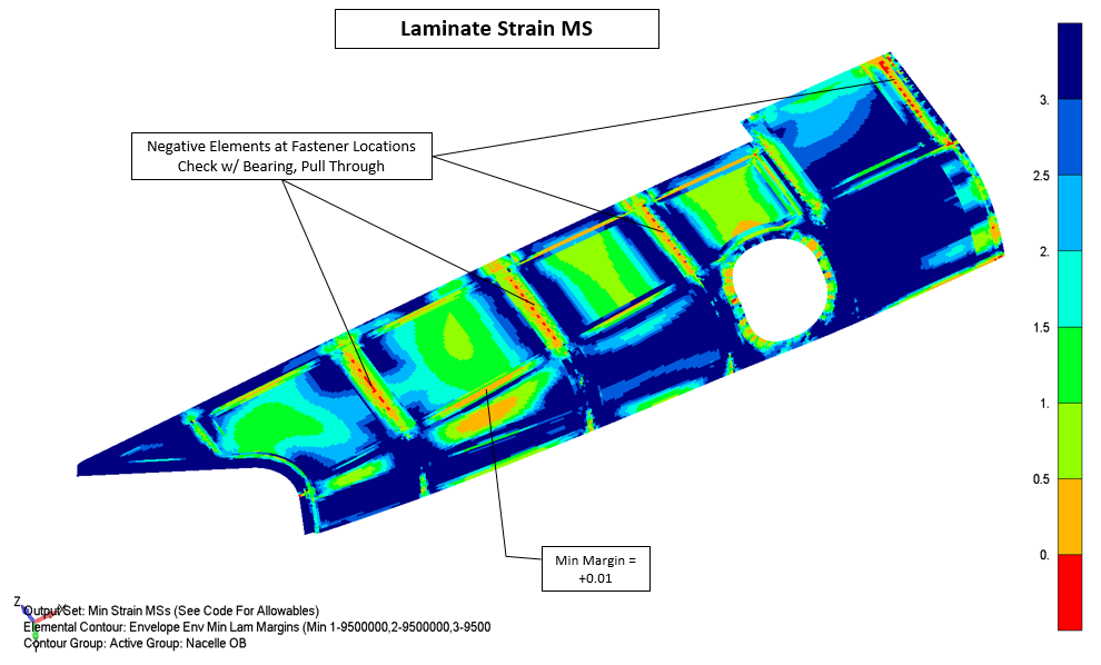
All components had minimum margins close to zero. This approach ensured that all our components were just stiff enough and just strong enough to withstand predicted flight loads. Most of our structure was sized by abrupt yaw cases and hammershock cases.

Carbon-fiber Ply Design
I learned CPD from our leading composites expert at Boom. As a result, I was able to achieve within 2% of the predicted FEM stiffness in the as-built composite parts. The stiffness and quality of a composite part relies heavily on how the plies are spliced and darted and what seed points are chosen. Flattened patterns of nacelle plies are shown in the image to the left.

Assisted Fabrication
at the Vendor
Due to weight savings optimization, the outboard inlet composite parts increased in complexity. Some composite frames (like the one shown below) had over 200 carbon fiber cut pieces that all needed to be placed with high accuracy. The inlet ducts were also extremely challenging to fabricate because the tool needed to be chiseled out by hand after the parts finished curing in the autoclave. As a result, it was vital to have engineering support on-site. While supporting in an engineering capacity, I also had the opportunity to layup parts I designed with experienced composite technicians.

View into the righthand inlet duct as the CFOAM tool is being chiseled away

View of core being laid up on the lefthand inlet duct.

View of a tight corner in one of the outboard inlet frames. Tight corners required many darts and patch plies

Supported Assembly and Nonconformances
The outboard inlets were jigged, bonded, and fastened in five weeks. This accelerated schedule required copious engineering support and diligent planning ahead. On the engineering side, I created work instructions, reviewed bond gaps with metrology, checked bond fillets, and create fastener vector files. However, I also got my hands dirty; I helped glue jigs to aircraft hardware, bond prep carbon fiber components, mix adhesive, fillet critical bonds, and pop a few rivets. This phase of the build has been my favorite aspect of the design cycle!
